
Board-to-Board Connector Selection Guide: A Practical Engineering Workflow
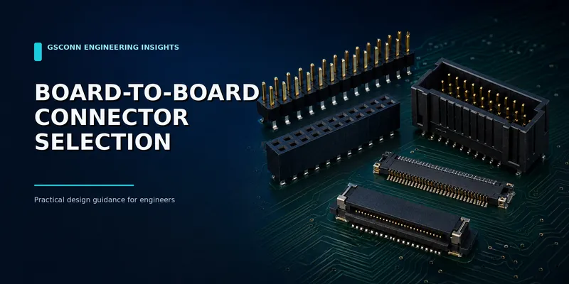
Board-to-Board Connector Selection Guide: A Practical Engineering Workflow
Choosing a board-to-board (B2B) connector is not simply a matter of matching pitch and pin count. The connector also defines board spacing, assembly tolerance, serviceability, signal integrity, current density and, often, the mechanical architecture of the enclosure.
This guide turns those requirements into a practical selection workflow. It is intended for engineers and sourcing teams comparing pin headers, shrouded headers, mezzanine connectors, floating connectors and high-speed interconnects.
Short answer: Start with board orientation and available space. Then define circuits, current and data-rate requirements. Finally, check alignment tolerance, environment, mating life, assembly process and supply-chain constraints. A connector should pass every gate—not merely fit the footprint.
Quick selection matrix
| Design requirement | Strong starting point | Typical pitch range | Main trade-off |
|---|---|---|---|
| Lowest cost and easy prototyping | Pin header + female header | 1.00–2.54 mm | Limited keying and signal-integrity control |
| Polarized cable or board connection | Box/shrouded header | 1.27–2.54 mm | Larger PCB footprint |
| Compact parallel PCB stack | Mezzanine plug + receptacle | 0.35–1.27 mm | Tighter placement and coplanarity requirements |
| Vibration or assembly misalignment | Floating B2B connector | 0.5–0.8 mm typical | Higher component cost |
| Multi-gigabit differential links | Characterized high-speed B2B | Product-specific | Requires channel-level SI validation |
| Replaceable daughter card | Card-edge or right-angle B2B | Product-specific | Mechanical support and contact wear |
| Mixed power and signals | Hybrid B2B connector | Product-specific | Thermal and creepage constraints |
Pitch ranges are representative, not universal. Always confirm the selected series drawing and qualification report.
1. Define the mechanical architecture first
The first decision is how the two PCBs meet:
| PCB relationship | Common solution | Questions to resolve |
|---|---|---|
| Parallel, face-to-face | Mezzanine or floating B2B | Required mated height? PCB bow? Blind mating? |
| Perpendicular | Right-angle header, card-edge or dedicated orthogonal connector | Is a bracket or guide rail required? |
| Coplanar | Right-angle pair, edge connector or bridge board | Can the assembly tolerate connector overhang? |
| Cable-linked | Box header + IDC socket or wire-to-board system | Is polarization, latching or strain relief required? |
For parallel stacks, specify the mated stack height, not just the height of one connector half. Include PCB thickness, component keep-out zones and tolerance stack-up. If the housing or enclosure locates both boards independently, a floating connector may prevent the connector solder joints from absorbing assembly error.
2. Count circuits by function—not only by total pins
Create a pin-assignment budget before selecting a part:
- Power and return contacts
- Single-ended signals
- Differential pairs
- Ground pins used for shielding
- Detect, enable or sequencing pins
- Reserved pins for future revisions
A 60-position connector does not necessarily provide 60 usable signal contacts. High-speed pairs may require adjacent grounds, while power contacts may need to be paralleled and distributed across the housing to control temperature rise.
For power, evaluate the complete mated pair. The female spring contact, termination, PCB copper and neighboring energized contacts may set the limit before the solid male pin does.
3. Separate “protocol name” from signal-integrity evidence
Labels such as “PCIe-ready” or “high-speed” are useful only when supported by data for the exact connector and stack height. Ask for:
- Differential impedance target
- Insertion loss, return loss and crosstalk
- Touchstone S-parameter files
- Test fixture and de-embedding method
- Pin map used for the published performance
- Supported mated heights and PCB launch recommendations
PCI Express link rates are expressed in GT/s. For example, PCIe 5.0 operates at 32.0 GT/s. The connector is only one element of the channel; package, PCB traces, vias, cables and other connectors share the loss and reflection budget.
4. Treat current rating as a thermal result
Current rating depends on temperature rise, ambient temperature, contact resistance, copper area and the number of simultaneously loaded contacts. A single-contact headline rating should not be multiplied by the total pin count.
Use this sequence:
- Define continuous, peak and inrush current.
- Identify the hottest realistic ambient temperature.
- Allocate power and return contacts with current-sharing margin.
- Obtain the manufacturer’s derating curve for the selected housing and termination.
- Validate the assembled PCB pair at worst-case current and airflow.
IEC 60512-5-2 provides a standardized approach for current-temperature derating, but the final rating remains product- and application-specific.
5. Match the connector to assembly capability
| Connector style | Common process | Manufacturing checks |
|---|---|---|
| 2.54 mm pin header | Through-hole, press-fit or SMT | Pin straightness, solder fill, coplanarity |
| Fine-pitch mezzanine | SMT reflow | Placement accuracy, stencil design, warpage, AOI |
| Floating B2B | SMT reflow | Float neutral position, housing clearance, fixture design |
| Card-edge | SMT/through-hole receptacle + plated PCB edge | Bevel, gold-finger finish, PCB thickness |
For lead-free reflow, verify the exact housing resin grade and reflow profile. “LCP,” “PPA” or “PBT” describes a polymer family, not a universal temperature rating.
6. Check environment and service life
The same connector can perform very differently in a laboratory and inside a vehicle, server or outdoor controller. Add these requirements to the specification:
| Stress | What to specify or test |
|---|---|
| Vibration and shock | Retention, contact normal force, fretting performance |
| Temperature cycling | Housing stability, contact stress relaxation, solder-joint strain |
| Humidity or condensation | Plating system, insulation resistance, moisture behavior |
| Dust or contamination | Shrouding, wiping action, covers and cleaning process |
| Repeated service | Rated mating cycles, keying, latch durability and field handling |
| Chemicals | Resin and plating compatibility with cleaners, oils or sterilants |
If technicians will mate the connection, polarization and clear visual orientation are usually worth more than a small saving in connector cost.
7. Compare the main B2B connector families
Pin header and female header
Best for low-cost, low-to-moderate-density signals, prototypes and established industrial designs. They offer many heights and orientations but generally provide limited misalignment accommodation and no controlled-impedance performance unless the series is specifically characterized.
Box or shrouded header
Adds pin protection and polarization, and may add a latch. It is a strong choice for IDC ribbon cable assemblies, serviceable internal wiring and applications where reverse mating must be discouraged.
Mezzanine connector
Provides dense parallel-board stacking with defined mated heights. Selection is driven by pitch, position count, stack height, electrical performance and allowable alignment error.
Floating B2B connector
Uses controlled movement in one or more axes to absorb assembly misalignment. It is useful when two boards are fixed to separate chassis features or when vibration and tolerance accumulation would otherwise load solder joints.
High-speed B2B connector
Uses a contact and ground architecture characterized for differential channels. Select it from S-parameters and the complete channel budget, not from pitch or an advertised data rate alone.
8. A practical RFQ checklist
Send the following information when requesting a recommendation or quotation:
- Board orientation and a mechanical drawing
- Pitch, position count and preferred row count
- Mated stack height or right-angle geometry
- Continuous/peak current and number of loaded power contacts
- Interface or maximum edge rate
- Differential impedance target and preferred pin map
- Operating temperature, vibration, humidity and contamination
- Required mating cycles and latch/keying needs
- SMT, through-hole or press-fit termination
- Annual volume, prototype quantity and target production date
- Required compliance documents and test reports
This information allows suppliers to compare viable families instead of quoting the nearest footprint match.
Common selection mistakes
- Choosing pitch before defining stack height. The result may fit the PCB but not the enclosure.
- Multiplying one-contact current by every pin. Adjacent contacts thermally interact.
- Assuming every fine-pitch connector supports high-speed links. Geometry and S-parameter evidence matter.
- Ignoring PCB bow and placement tolerance. Fine-pitch mezzanine connectors have limited capture range.
- Treating gold color as a plating specification. Specify the complete finish system and thickness at the contact zone.
- Using rated mating cycles as field life. Dust, side load, vibration and handling can change the result.
FAQ
What is the most common board-to-board connector?
Pin headers remain common for simple, low-cost designs. Compact products increasingly use fine-pitch mezzanine connectors because they provide more circuits in less area and a controlled stack height.
When should I use a floating connector?
Use one when the boards are independently located, the mating operation is blind, the assembly sees vibration, or the tolerance analysis shows that a rigid connector would transfer significant load into the solder joints.
Can a standard pin header carry PCIe?
A short, carefully designed interconnect may function at some speeds, but a standard pin header normally lacks controlled-impedance characterization. For a production PCIe channel, choose a connector with relevant S-parameter data and validate the complete channel.
How early should the connector be selected?
Before the enclosure, PCB keep-outs and mounting features are frozen. Connector selection affects all three.
Need help narrowing the options?
Send GSConn your board layout constraints, stack height, pin map, current, interface, environment and annual volume. The engineering team can propose a connector architecture and identify which drawings, samples and validation data are needed before design freeze.
Sources and further reading
- https://webstore.iec.ch/en/publication/2410
- https://webstore.iec.ch/en/publication/2365
- https://pcisig.com/what-bit-rates-does-pcie-50-specification-support-and-how-does-it-compare-prior-pcie-generations
- https://www.te.com/content/dam/te-com/documents/industrial-intelligent-buildings/global/Connectors%20101_What%20Lighting%20Designers%20Need%20to%20Know_0217.pdf
Related guides: b2b-pin-header-female-header-guide.md · b2b-box-header-vs-pin-header.md · b2b-mezzanine-connector-guide.md · b2b-high-speed-connector-guide.md
Related reading on GSConn
- Wire-to-Board vs Board-to-Board Connectors
- Industrial USB Connector Guide
- IP67 vs IP68 USB Connector
- Stacked USB Connector Guide
- Request a Quote
Engineering references
- Product drawing, datasheet, material declaration and qualification report for the selected connector series
- IPC land-pattern and acceptability guidance applicable to the PCB assembly class
- Project-specific vibration, shock, thermal and electrical requirements