
Floating vs Rigid Board-to-Board Connectors: Which Should You Use?
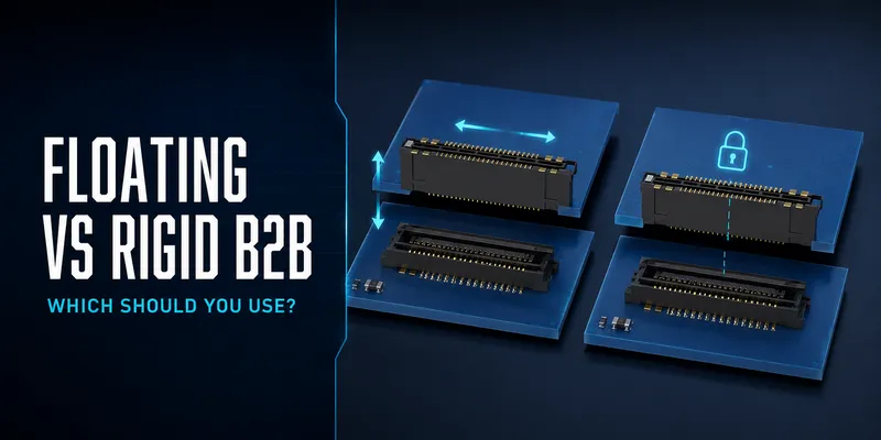
Floating and rigid board-to-board (B2B) connectors solve the same basic problem—connecting two PCBs—but manage mechanical variation in different ways. A rigid connector relies primarily on accurate board position and stable mechanical support. A floating connector adds a defined movement window that can reduce stress from relative board displacement.
The right choice is not determined by connector price alone. It depends on the assembly tolerance, number of mating interfaces, enclosure design, vibration and temperature exposure, electrical performance, manufacturing yield, and service risk.
Decision matrix
| Consideration | Rigid B2B is often suitable when… | Floating B2B is worth evaluating when… |
|---|---|---|
| Board alignment | One well-located interface has controlled datums | Relative position is harder to control or multiple connectors must mate |
| Mechanical environment | The assembly is stable and well-supported | Vibration, shock, flex, or thermal movement may create relative displacement |
| Product profile | Minimum height is a primary requirement | There is space for a compliant interface |
| Production approach | Precision fixture and alignment control are already proven | Blind mating, tolerance absorption, or rework reduction is valuable |
| Electrical requirement | A rigid product meets the channel and power needs | A floating product with verified electrical data meets them too |
1. How rigid and floating interfaces react to movement
A rigid B2B connector typically locks two PCB-mounted halves at a fixed location. If the boards remain correctly positioned and supported, this is a simple and reliable architecture. If the relative position changes, the system must absorb the resulting load through board flex, housing geometry, mechanical supports, or the solder joints.
A floating B2B connector is designed so that part of the interface can move within a defined range. The movement may be lateral X/Y, limited Z compliance, or a combination documented by the supplier. This can reduce transmitted load, but it does not make the system immune to excessive offset, board bow, rotational error, improper mated height, or poor enclosure support.
2. Compare the design trade-offs
| Parameter | Rigid B2B | Floating B2B | What to verify |
|---|---|---|---|
| Alignment | Depends on PCB and fixture control | Provides a specified mating/operating window | Full tolerance stack-up |
| Multi-connector mating | May be sensitive to differential position | Can improve mating margin | Connector coordinates, guides, and total mating force |
| Vibration response | Depends on system stiffness and support | Adds controlled compliance | System-level vibration/shock test |
| Height and volume | Often offers lower-profile options | Mechanism may require more space | Mated-height and keep-out drawings |
| Assembly | Fixed geometry may require precise alignment | Can simplify blind or tolerance-sensitive mating | Trial build, placement, mating sequence |
| Signal integrity | Depends on product family/channel design | Depends on product family/channel design | SI data for the exact part and stack-up |
| Cost | Often lower component cost | May have a mechanism premium | Total cost of quality and field risk |
3. Choose floating when the tolerance stack-up says you need it
The strongest reason to select a floating B2B connector is a documented relative-position problem. Build a stack-up that includes board fabrication, connector placement, datum strategy, fixture tolerances, board rotation, thermal expansion, board flatness, and dynamic loading.
Floating is especially useful in these situations:
- Several connectors mate between the same board pair.
- A service module must blind-mate into a constrained enclosure.
- Large boards are restrained at different mechanical reference points.
- The product sees vibration or movement that can cause board-to-board displacement.
- A rigid connector would force impractical tolerances on the PCB, fixture, or enclosure.
For the calculation approach, see How to Select Floating Connector Travel.
4. Do not use floating as a substitute for mechanical design
Even a high-travel connector needs a sound mechanical architecture. Define standoffs, guide features, board support, fastener locations, cable loads, service actions, and vibration paths. Keep the moving interface clear of nearby components and mechanical obstructions.
| Problem | Why float alone is not enough | Recommended control |
|---|---|---|
| Large board bow | Movement may be out of plane or create contact with components | Standoffs, board-stiffness review, Z-tolerance check |
| Excessive rotation | Lateral offset grows with distance from the datum | Locate datum/guide features and analyze rotation |
| Heavy board or user-applied force | Connector may become a structural support | Add mechanical supports and load paths |
| Multiple connectors | Total mating force can become high | Define sequencing, supports, and guide features |
| Incorrect board spacing | Contact engagement can be incomplete | Select proper mated height and verify cross-section |
5. Electrical performance: evaluate the selected series, not the category
Neither “rigid” nor “floating” alone predicts high-speed or power performance. For a signal channel, ask for the appropriate electrical data for the selected part, pin map, and reference board. For a power path, use the product’s derating information under the actual loading, adjacent-contact, and ambient conditions.
An architecture decision should include:
- Contact assignment and ground strategy
- Return-path continuity across the connector
- Insertion loss, return loss, and crosstalk data where relevant
- Current derating and temperature-rise behavior
- Insulation, creepage, and clearance requirements for the product voltage
- End-of-line and field-service requirements
6. Total cost: look beyond unit price
A rigid connector may cost less per part, but the more economical system is the one that meets yield and reliability targets. Consider the cost of alignment tooling, tighter PCB tolerances, assembly time, inspection, rework, warranty exposure, and redesign risk.
| Cost area | Questions to ask |
|---|---|
| Component | Is the price difference material at production volume? |
| PCB and fixture | Does a rigid design require tighter tolerances or more complex guides? |
| Assembly | Which option gives a wider, validated process window? |
| Test | Can the system be checked efficiently for mate and continuity? |
| Field performance | What is the cost if connection reliability is inadequate in use? |
7. Migration checklist: replacing rigid with floating
- Confirm that the required mated height fits the enclosure and component envelope.
- Replace the land pattern only with the supplier-approved footprint and keep-out zone.
- Review contact numbering, keying, and signal/power assignment.
- Analyze alignment travel and the new mating sequence.
- Update placement, stencil, reflow, AOI, and functional-inspection requirements.
- Add or revise standoffs, guides, and board supports if necessary.
- Complete a pilot build and application-specific validation before release.
FAQ
Will a floating connector fix a cracked solder-joint problem?
It may reduce displacement-related stress, but first determine the actual failure mechanism. Board support, reflow quality, connector retention, enclosure loading, and vibration profile may all contribute.
Is rigid B2B always better for high-speed signals?
No. Compare qualified product data and the final channel performance. A suitable floating series may meet the requirement; a rigid series may not, and vice versa.
Can I change only the connector and keep the same footprint?
Usually no. Confirm the land pattern, hold-downs, keep-out, height, mating geometry, and pinout from the product drawing.
Start with a system review
Share the board-pair drawing, connector positions, mated-height target, signal/power requirements, environmental profile, and current assembly issue. The GSConn engineering team can then compare rigid and floating candidates using the actual design constraints.
Related articles: Complete Floating B2B Guide · Float Range Selection · Stacking Height Selection · PCB Layout & Assembly
Related reading on GSConn
Engineering references
- Product drawings and qualification data for the candidate connector series
- PCB, enclosure, and assembly tolerance documentation
- Application-specific electrical, thermal, vibration, and shock test requirements