
Floating Board-to-Board Connectors: Design and Selection Guide
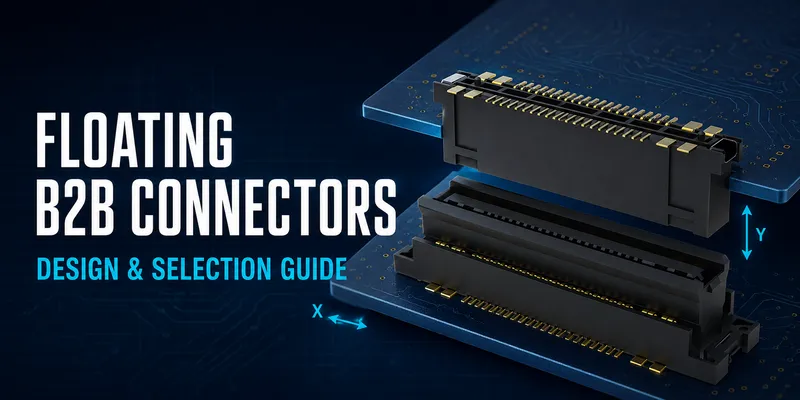
Floating board-to-board (B2B) connectors are used when two printed circuit boards must remain electrically connected even though their relative position is not perfectly fixed. Instead of forcing assembly error, board warp, thermal movement, or vibration directly into the solder joints, the connector provides a defined amount of mechanical compliance.
That compliance is valuable in multi-board industrial equipment, displays, robotics, mobile equipment, and automotive electronic modules. It is not a substitute for a tolerance analysis: the connector must be selected from the actual mechanical envelope, required electrical performance, and the supplier’s approved product data.
At a glance: what to define first
| Design input | Why it matters | What to obtain from the supplier |
|---|---|---|
| X/Y misalignment budget | Determines the needed lateral travel | Travel definition, allowable offset, mating window |
| Board-to-board distance | Determines the mated height | Mated-height drawing and Z-tolerance limits |
| Number and locations of connectors | Drives differential misalignment and mating force | Multi-connector mating guidance |
| Signals and current per contact | Determines contact system and pin assignment | Current derating and SI data for the exact part |
| Environment and service life | Determines materials, retention, and validation | Temperature, vibration, shock, and cycling reports |
| PCB process | Determines footprint and assembly yield | Land pattern, stencil recommendation, reflow limit |
1. What is a floating B2B connector?
A conventional B2B connector mates two PCB-mounted halves at a fixed position. A floating B2B connector adds controlled movement—usually lateral X/Y movement and, for some families, limited Z compliance—to one half or to the mated interface. The electrical contact system remains engaged while the floating element moves within its rated travel.
The exact construction varies by series. Do not assume that every product provides X, Y, and Z travel, or that its stated travel is available in every direction simultaneously. Read the dimensional drawing and mating specification for the configured part number.
2. When does floating add value?
Floating B2B connectors are most useful when one or more of the following conditions applies:
- Two or more connectors must mate between the same boards.
- The boards are large enough for thermal expansion or warpage to matter.
- Assembly is blind-mate or has limited visual access.
- The equipment sees vibration, shock, or repeated temperature change.
- A rigid connector would require overly tight fixture, PCB, or placement tolerances.
For a single, well-constrained board pair in a stable enclosure, a rigid B2B connector may be simpler and lower cost. The decision should consider the total installed cost, including fixtures, rework, yield, and field reliability—not just the connector price.
3. The key selection parameters
3.1 Pitch and pin count
Pitch is the center-to-center spacing between adjacent contacts. Finer pitch increases pin density but reduces routing and assembly margin. Select the smallest pitch that meets the required pin count and enclosure area while remaining compatible with your PCB fabricator, assembler, inspection capability, and repair process.
| Selection question | Practical guidance |
|---|---|
| Is PCB area the dominant constraint? | Consider a fine-pitch family, then verify stencil and placement capability. |
| Is vibration margin and easy assembly more important? | A larger-pitch family may give more robust pads and clearer inspection. |
| Are power and signal mixed? | Use a hybrid contact system or separate the power path; do not infer power capability from pitch alone. |
| Is high-speed data present? | Obtain insertion loss, return loss, crosstalk, and channel compliance data for the exact stack-up. |
See B2B Connector Pitch Selection for a focused comparison.
3.2 Float range and tolerance stack-up
Float range is not simply an assembly-error allowance. It must cover the relative displacement that can occur between the two mating halves after PCB fabrication, connector placement, fixture tolerance, board warpage, thermal expansion, and operational motion are considered.
Use a vector tolerance analysis rather than adding only nominal values. Reserve margin for mating lead-in, rotation, and manufacturing variation. A useful starting point is:
required travel ≥ worst-case relative offset + mating margin
The remaining margin must stay inside the supplier’s specified operating window. For a worked method and checklist, see How to Select Float Range.
3.3 Mated height and Z compliance
Mated height is the specified board-surface-to-board-surface distance after the connector pair is fully engaged. It is a fixed product dimension, not an enclosure dimension that can be freely adjusted.
Choose a mated height that clears the component envelope between the boards, includes board-thickness and mounting tolerances, and leaves an appropriate non-contact clearance. If multiple connectors are used, verify board parallelism and whether the selected product has documented Z compliance. Mechanical standoffs should carry board weight and external loads; the connector should not be the only structural support.
See Stacking Height Selection.
3.4 Electrical performance
Current rating depends on contact design, number of energized adjacent contacts, copper temperature rise, plating, ambient temperature, and wiring or trace resistance. Use the configured-part derating curve—not a generic current value.
For differential pairs or fast single-ended links, treat the connector as part of the complete channel. Ask for test methods, reference board details, and S-parameter files where available. Validate the final PCB stack-up, via transitions, routing, and connector assignment as one system.
4. Floating versus rigid B2B connectors
| Factor | Rigid B2B | Floating B2B |
|---|---|---|
| Alignment allowance | Primarily provided by board/fixture precision | Provides a documented movement window |
| Multiple-connector mating | Can require tight positional control | Can simplify mating when travel is correctly sized |
| Vibration and movement | Depends heavily on enclosure support and solder-joint design | Adds compliance, but still needs system validation |
| Profile and cost | Often lower | May be larger or cost more because of the mechanism |
| Best fit | Stable, constrained assemblies | Tolerance-sensitive or moving assemblies |
Read the fuller comparison in Floating vs Rigid Board-to-Board Connectors.
5. Layout and assembly rules that prevent design-in problems
- Use the supplier’s recommended land pattern and keep-out drawing; generic pad sizes are not a replacement.
- Preserve the stated clearance around the moving element and mating path. Keep copper, components, screws, and shields outside that dynamic envelope.
- Include local fiducials and appropriate PCB tooling for fine-pitch placement.
- Use the documented reflow profile, coplanarity limit, and stencil recommendation for the selected housing material.
- For multiple connectors, define the mating sequence, board support, and maximum insertion force before building a pilot assembly.
- Inspect both solder quality and free movement after reflow using a controlled, non-damaging functional check.
More details are available in the PCB Layout and Assembly Guide.
6. Validation plan: test the installed system
An individual connector qualification report is valuable, but it does not prove the reliability of the final assembly. Build a validation plan around your application:
| Test area | What to verify |
|---|---|
| Mechanical fit | Mating window, travel remaining after assembly, board support |
| Electrical | Continuity, contact resistance trend, insulation and dielectric requirements |
| Environmental | Temperature exposure and cycling relevant to the use location |
| Dynamic | Vibration and shock profile representative of the mounted equipment |
| Signal integrity | Channel performance with the final PCB stack-up and cable/board interfaces |
| Manufacturing | Placement yield, reflow robustness, inspection, rework, and end-of-line test |
Define pass/fail criteria before the test starts. The relevant standard, severity, sample size, and acceptance limits should be agreed with the end customer and connector supplier.
FAQ
Does a floating connector eliminate the need for alignment features?
No. It widens the acceptable mating window but does not compensate for unlimited offset, rotation, board bow, or incorrect mated height. Use guide features and rigid mechanical support when the application needs them.
Can I replace a rigid B2B connector without changing the PCB?
Usually not. Verify the footprint, hold-downs, keep-out zone, height, pin assignment, and mating geometry. Treat it as a controlled PCB and assembly change.
Does more float always mean a better connector?
No. More travel may require more space, affect the mechanical architecture, and still cannot replace a poor tolerance stack-up. Select the smallest documented travel that leaves adequate margin.
Start a design-in review
Share the connector count and locations, desired mated height, required pin count, current per contact, signal types, PCB drawing, and environmental profile. With those inputs, the GSConn engineering team can propose candidate part numbers, footprint files, and a test plan that are specific to the application.
Related articles: Float Range Selection · Pitch Selection · PCB Layout & Assembly · Industrial Robotics
Related reading on GSConn
Engineering references
- Product drawing, datasheet, material declaration, and qualification report for the selected connector series
- IPC land-pattern and acceptability guidance applicable to the PCB assembly class
- Project-specific vibration, shock, thermal, and electrical requirements