
Floating B2B Connectors for Industrial Robotics and Automation
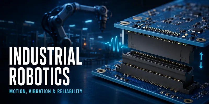
Industrial robots, automated guided vehicles (AGVs), autonomous mobile robots (AMRs), and motion-control equipment often package several PCBs in a compact controller or drive. These assemblies can experience machine vibration, acceleration, connector mating during service, board flex, and temperature change. A floating board-to-board connector can help manage the resulting relative movement—provided the complete mechanical and electrical system is designed around it.
The goal is not to choose the largest available travel. It is to retain a verified mating and operating margin after the controller, boards, enclosure, and production process are combined.
Where floating B2B connectors can help
| Robotics subsystem | Typical interconnect challenge | Design focus |
|---|---|---|
| Servo drive/controller board | Multiple board interfaces in a limited enclosure | Differential tolerance, total mating force, thermal path |
| Robot joint electronics | Compact package with motor-induced vibration | Board support, retention, EMC, temperature |
| AGV/AMR controller | Mobile vibration, shock, and service access | Guides, shock profile, connector clearance |
| Safety and I/O module | Mixed low-level signals and field interfaces | Pin assignment, isolation, continuity verification |
| Vision or sensor processor | High-speed signals in a constrained package | Channel performance, grounds, mating height |
1. Start with the real mechanical load case
“Industrial robotics” is not one vibration condition. The relevant profile depends on machine type, mounting location, tool load, travel speed, motor characteristics, and enclosure stiffness. A cabinet-mounted controller may see a different spectrum than a board in a mobile vehicle or near a spindle.
Before selecting a connector family, define:
- Equipment location and mounting orientation
- Expected vibration and shock requirement or measured profile
- Temperature, humidity, contamination, and cleaning exposure
- Board size, thickness, supports, and mounting points
- Connector count, positions, and service/mating operations
- Expected product life, maintenance interval, and acceptance criteria
Use an application-specific test plan rather than a generic “robotics-rated” claim.
2. Multi-board controller architecture: manage differential offset
Several connectors between one board pair can create a difficult mating condition because the last connector must accommodate the accumulated relative position of both boards. The primary issue is not the number of pins; it is the position and rotation of each interface relative to common datums.
| Architecture feature | Risk if not controlled | Recommended action |
|---|---|---|
| Multiple connectors on the same board pair | Binding or incomplete engagement | Perform an X/Y/Z and rotation stack-up for every connector location. |
| Large board span | Thermal movement and board deflection | Add standoffs and analyze support locations. |
| Blind-mate service module | Initial angle/offset during insertion | Add lead-in guides and define the mating path. |
| High pin-count interface | Higher total insertion force | Size the fixture, supports, and operator/automation process. |
| Remote connectors from locating pins | Rotation becomes amplified | Locate guides/datum features strategically. |
For the detailed method, see How to Select Floating Connector Travel.
3. Signal and power planning for robot electronics
Robot control boards can include encoder, sensor, network, control, brake, and power signals. Assign the interface from the electrical architecture—not from an arbitrary contiguous pin order.
| Signal group | Design considerations |
|---|---|
| Encoder and sensor signals | Shielding/grounding strategy, noise margin, reference return path |
| Industrial communication | Controlled impedance, pair routing, EMC/ESD scheme, protocol requirements |
| Analog feedback | Separation from switching nodes, low-noise reference, pin placement |
| Safety-related I/O | System safety architecture, diagnostics, isolation, and end-of-line test |
| Local power | Current derating, temperature rise, voltage drop, protection, and connector approval |
If a connector carries both power and sensitive data, verify the supplier’s recommended pin map and run electrical/thermal validation under worst-case adjacent-contact loading. A product’s rated current should not be treated as a system power budget.
4. Build the mechanical architecture around the connector
Floating travel reduces displacement stress; it does not replace structural support. Define hard stops, standoffs, screws, guides, rails, and cable strain relief so boards do not use the connector as their only support.
Practical design rules
- Support boards close enough to the connector that mating force does not bend the PCB beyond its allowable deflection.
- Use a controlled approach direction; avoid side-loading a mated connector during service.
- Keep components, fasteners, shields, and cable features outside the connector’s dynamic travel and service envelopes.
- Check board parallelism and mated-height tolerance as well as lateral movement.
- Consider conductive shielding, grounding, and enclosure seams as part of the EMC design, not as an afterthought.
5. Validation for robotics applications
Connector validation should represent the completed board assembly and enclosure. The selected test standard, severity, duration, sample size, and acceptance limits should come from the machine specification, customer requirement, and risk analysis.
| Validation area | Typical evidence |
|---|---|
| Mechanical mate | Mating force, full engagement, travel remaining, guide operation |
| Electrical | Continuity monitoring, contact-resistance trend, insulation as applicable |
| Vibration and shock | System-specific profiles with the boards mounted as in production |
| Thermal | Temperature exposure/cycling with actual restraints and power dissipation |
| EMC | Emissions/immunity test on the intended enclosure and cabling arrangement |
| Manufacturing | Placement yield, reflow qualification, inspection, and rework limits |
IEC 60068 test methods are often used as a basis for environmental testing, but the actual profile must be selected for the product—not copied from a general article.
6. Common design mistakes
| Mistake | Why it creates risk | Better practice |
|---|---|---|
| Choosing travel from robot type alone | Actual board movement can be lower or higher | Use a stack-up and measured/required load profile. |
| Treating the connector as a board support | Loads can reach solder joints and contacts | Use dedicated standoffs and guide features. |
| Allocating power contacts without derating | Adjacent contact heating may reduce capacity | Apply product-specific derating and thermal test. |
| Ignoring service mating | Field insertion can differ from factory assembly | Test the actual operator/tool/fixture process. |
| Validating only an isolated connector | System supports and enclosure change the stress | Test production-intent board and housing assemblies. |
FAQ
Are floating connectors necessary in every industrial controller?
No. A rigid B2B connector may be appropriate for a stable, well-controlled board pair. Floating is most valuable when the tolerance stack-up, service mating, or environmental movement requires compliant travel.
How do I select travel for an AGV or AMR?
Start with board and enclosure geometry, then add the relevant mobile vibration/shock requirement and temperature movement. Select the connector only after checking the full relative-position envelope.
Can one floating connector carry encoder, communication, and power?
Possibly, if the chosen series is qualified for the electrical requirements and the pin map, derating, signal integrity, EMC, and safety needs are validated. Separating interfaces is often preferable where requirements differ substantially.
Start a robotics connector review
Provide the controller mechanical model, PCB outlines and support points, connector coordinates, target mated height, pin map, current per contact, communication interfaces, test profile, and service-mating description. Those inputs allow the GSConn engineering team to prepare an application-specific recommendation and validation plan.
Related articles: Complete Floating B2B Guide · Float Range Selection · PCB Layout & Assembly · Floating vs Rigid B2B
Related reading on GSConn
Engineering references
- Selected connector drawings, derating curves, and qualification documentation
- Machine vibration/shock requirements or measured operating data
- Applicable IEC 60068 methods and the project’s EMC, safety, and manufacturing requirements