
Floating B2B Connectors for Automotive Electronics
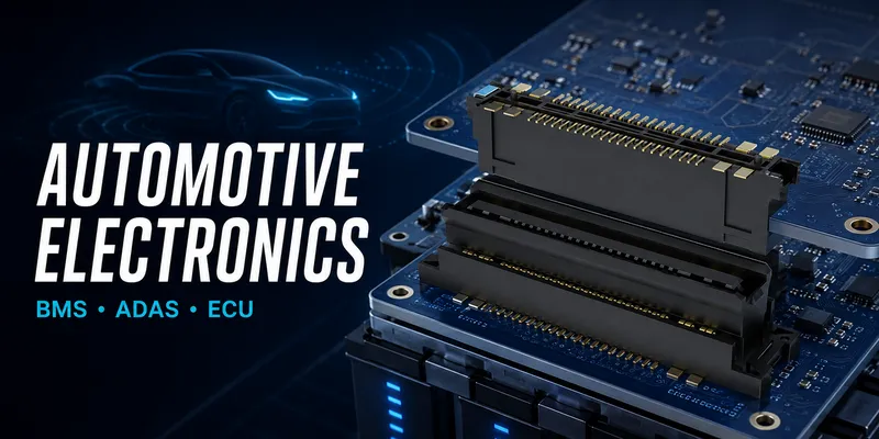
Automotive electronic modules combine tight packaging with temperature change, vibration, shock, long service life, and strict traceability. Where multiple PCBs must mate within a housing, a floating board-to-board connector can provide useful alignment and movement margin. However, the product must be selected and validated against the actual vehicle program, mounting location, and OEM or Tier-1 requirements.
An “automotive” label is not enough. The engineering evidence must match the assigned function, electrical load, environmental location, production-control plan, and customer documentation.
Important qualification note
AEC-Q200 is a stress-test qualification for passive components. It should not be presented as a generic connector qualification. For automotive connector systems, requirements are often defined by the customer/OEM, an applicable connector test specification such as USCAR-2 or LV 214 where relevant, and the supplier’s documented product qualification. Confirm the applicable revision, scope, and acceptance criteria with the program team.
Typical applications and design focus
| Module | Why a floating interface may help | Key verification topics |
|---|---|---|
| Battery-management electronics | Multiple boards, thermal movement, constrained housing | Mated height, isolation, current derating, temperature, serviceability |
| ADAS camera/radar module | Compact package and alignment-sensitive assembly | Mechanical datum, signal integrity, EMC, temperature, optical interfaces |
| ECU/domain controller | Multi-board packaging and network/data interfaces | PCB support, high-speed channel, thermal path, vibration |
| Infotainment/display module | Packaging, service mating, and board alignment | Consumer-facing durability, EMC, mated height |
| Power electronics controller | Electrical separation and thermal/mechanical loading | Creepage/clearance, derating, vibration, heat, safety architecture |
1. Map the connector to the vehicle environment
The connector selection must begin with its real mounting location. Conditions in a cabin display, a sealed battery pack, an engine-bay ECU, and a wheel-adjacent controller can be very different.
| Requirement category | Questions to define |
|---|---|
| Temperature | What are the storage, operating, thermal-cycling, and local self-heating limits? |
| Mechanical loading | What vibration/shock profile applies at the installed location? |
| Atmosphere and contamination | Is there humidity, condensation, salt, fluid, dust, or outgassing exposure? |
| Electrical | What are voltage, current, transients, isolation, creepage, and clearance requirements? |
| Functional/safety impact | What failure modes, diagnostics, and documentation are required? |
| Production | What traceability, change control, PPAP/APQP, or customer-specific controls apply? |
Avoid using a broad temperature range or vehicle mileage statement as proof of suitability. The requirement needs to be tied to the actual program specification and evidence for the selected part number.
2. BMS and battery electronics: solve both mechanics and electrical separation
Battery-management assemblies may combine cell-sensing, temperature sensing, communication, and local power functions. The connector architecture must separate low-level signals from higher-current or higher-voltage functions as required by the system design.
BMS selection checklist
- Define the maximum working voltage, transient environment, required insulation coordination, and any service condition.
- Obtain the exact connector’s creepage/clearance, dielectric, insulation-resistance, and derating information.
- Model board position, mounting constraints, thermal growth, and the required travel after assembly.
- Verify contact allocation, ground/reference strategy, and network signal integrity.
- Confirm the enclosure support and retention architecture; do not let the connector carry pack or board structural loads.
- Validate the production-intent stack under the program’s environmental, electrical, and safety requirements.
3. ADAS, cameras, and domain controllers: protect the channel and mechanical datum
High-speed interfaces in cameras, radar, and domain controllers require a full channel review. Connector pitch or an advertised data-rate number alone does not demonstrate compliance. Request test data for the selected configuration, including the reference board, pin assignment, and measurement method.
Mechanically, sensor modules may also have optical or RF datums that must remain independent of connector mating force. Provide dedicated locating and support features so the connector’s compliance does not disturb lens, antenna, or heat-sink alignment.
4. Tolerance stack-up for multi-board modules
Use the PCB and housing datum scheme to calculate relative connector position. Include:
- PCB fabrication and placement variation
- Board rotation relative to guides and fasteners
- Mated-height tolerance and board parallelism
- Thermal movement between constrained reference points
- Vibration/shock displacement and enclosure deflection
- Service-mating angle and any module insertion path
The selected floating connector must retain margin within its documented operating displacement. For the method, see How to Select Floating Connector Travel.
5. Automotive validation: use the approved program plan
Automotive validation is a system activity. The connector’s internal qualification data is a starting point; production-intent module testing is still needed.
| Test area | What the plan should define |
|---|---|
| Mechanical | Mounting condition, vibration/shock profile, continuity-monitoring limits, and sample condition |
| Thermal/environmental | Temperatures, dwell, cycle count, humidity/condensation, and contamination exposure relevant to location |
| Electrical | Current loading, temperature rise, voltage/transient conditions, insulation, and contact-resistance criteria |
| Mating durability | Mating cycles, insertion tool/fixture, retention, and service actions |
| Manufacturing | Reflow limits, process capability, traceability, inspection, and change control |
| Program requirements | OEM/Tier-1 documents, applicable test methods, reporting format, and approval gates |
Do not claim compliance with a standard unless the supplier has provided evidence for the exact product/configuration and the customer has accepted its applicability.
6. Common automotive design errors
| Error | Risk | Better practice |
|---|---|---|
| Calling any heat-resistant B2B connector “automotive qualified” | Misleading program claim and qualification gap | Use exact part-number evidence and customer-approved requirements. |
| Applying AEC-Q200 directly to a connector | Incorrect standard scope | Use applicable connector/OEM validation documentation. |
| Ignoring adjacent-contact derating | Excess temperature rise | Evaluate worst-case load and thermal test. |
| Using float as structural support | Solder/contact stress in vibration | Design standoffs, guides, and load paths. |
| Validating a loose connector only | Installed module changes loading | Test the production-intent board, housing, and fixture. |
FAQ
Is a floating connector automatically suitable for an EV BMS?
No. Check voltage, insulation coordination, current derating, temperature, mechanical environment, functional-safety context, and program-specific validation for the chosen part number.
Which automotive standard should I cite?
Use only the standard or customer specification that applies to the product and has been reviewed by the program team. Connector suppliers should provide the relevant test evidence and scope.
Does more travel improve automotive reliability?
Only when the travel matches a documented displacement requirement and the rest of the mechanical system is properly supported. Excess travel does not replace a sound datum and support design.
Start an automotive design-in review
Share the vehicle module type, mounting location, required temperature and vibration profile, board stack-up, mated height, connector coordinates, pin map, current/voltage per circuit, insulation requirements, and the customer qualification plan. The GSConn engineering team can then assess actual part numbers, documentation, and a program-specific validation route.
Related articles: Complete Floating B2B Guide · Float Range Selection · PCB Layout & Assembly · Industrial Robotics
Related reading on GSConn
Engineering references
- Selected connector product drawing, material declaration, derating curves, and qualification report
- Applicable OEM/Tier-1 customer specification and approved validation plan
- Relevant connector-system test methods, including USCAR-2 or LV 214 only when applicable to the program